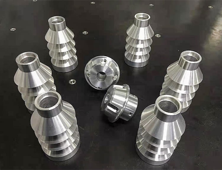
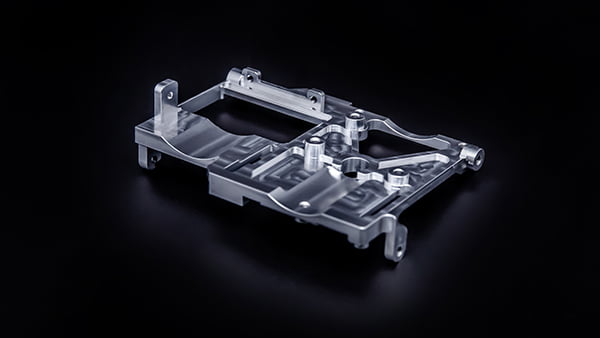
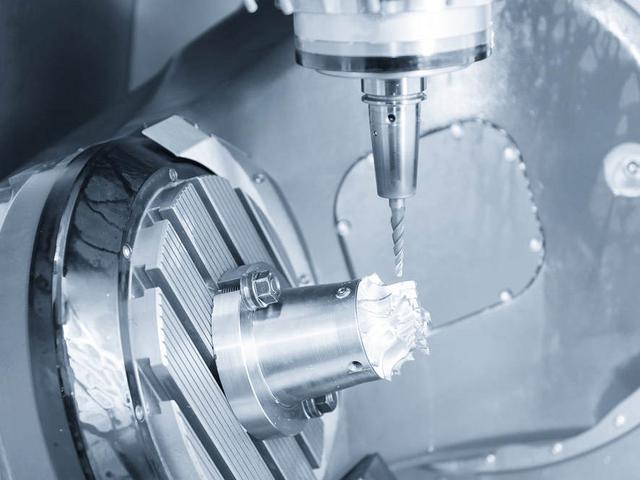
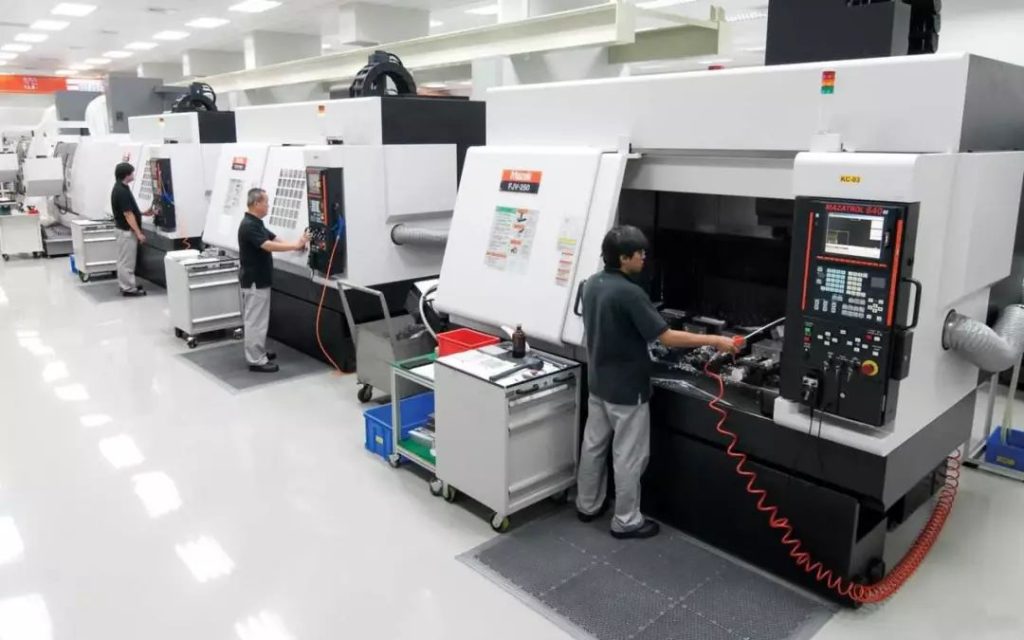
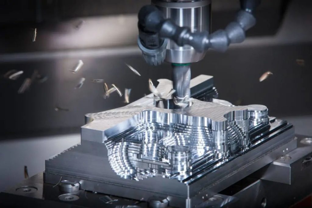
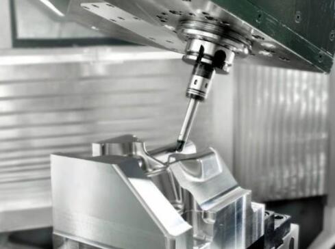
In the process of designing machine tools, cutting tools and auto parts, the challenge of efficiently milling various parts of micro models and micro parts is arduous. It can be said that it is also difficult to find the best tool path for the tool, because the machine operator may not see or hear its cutting at all. Different from the general milling operation, the operator cannot judge the performance of the tool in the cutting process in order to make the required changes and optimize the process. In addition, machining car parts may be suitable for "typical" milling workpiece tool path strategies, and may not always be optimized and reduced for micro milling.
Who proposed the experiment?
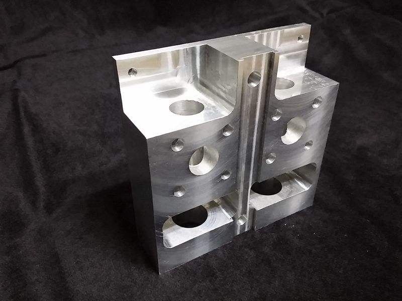
In addition, the small parts processing of medical, electronic and optical parts also has higher requirements. In view of this trend, the Fraunhofer Institute of Production Technology (IPT) in Aachen, Germany, recently launched a micro milling research project in cooperation with machine tool equipment manufacturers and mold manufacturers to develop efficient micro mold manufacturing strategies and processing methods. When developing micro milling NC software, they can effectively calculate tool movement with a tolerance of 0.1 μ m. Cimatron, a software company based in Novi, Michigan, also participated in the IPT project. The result of participation is to improve the performance of Cimatron E NC software by adding various functions of micro milling.
The following 5 issues should be considered when using the milling tool path:
Formulate the machining strategy suitable for micro milling. There are indeed similarities between high-speed machining and micro milling, such as avoiding sharp tool movement. When approaching the corner, the tool path should be circular, and the roundness depends on the machine tool and feed speed. When micro milling, it is useless to make a circle below a certain value. For example, 0.2 mm fillets are too large because typical micro machining spans are very small (close to 0.01 mm). In this example, the roundness value is 20 times the span value, which means that there will be a large gap between continuous machining, forming obvious concave convex lines, and the surface quality is poor.
The following 5 issues should be considered when using the milling tool path:
Milling is usually more efficient than straight milling. For micro milling, the decision to use up milling or down milling mainly depends on the characteristics of the machining car parts. Considering the precision characteristics of micro molds and micro parts, the up milling method is usually selected.
A combination of rough/finish milling processes may be required. Rough milling and finish milling are usually carried out separately, using different spindle speeds, feed rates and cutting depths. However, micro milling may not be possible, especially when machining high thin walls or hubs and bushings on small parts. The wall thickness after rough milling is not enough to support the finish milling operation, resulting in vibration or possible fracture of the finish milling, at least the wall finish is poor.
This is the knowledge of machining car part.

